The precise complex permeability can't be measured with a NanoVNA that simply, I think. But the initial permeability of around 800 provides some evidence that it really is a 43 mix.
Maybe, if we compare the heat image from a good unit in operation with the faulty one and thereby trace the lost power? 1-2W are being dissipated somewhere... Or, worst case, it's a confluence of smaller issues, all adding up.
(tr)uSDX power, efficiency and filter optimisation
-
hb9hem
- Posts: 36
- Joined: 07 Jan 2022, 04:39
Re: (tr)uSDX power, efficiency and filter optimisation
Last edited by hb9hem on 21 Mar 2022, 14:32, edited 1 time in total.
-
ve2rn

- Posts: 55
- Joined: 13 Jan 2022, 20:45
Re: (tr)uSDX power, efficiency and filter optimisation
I will receve today two B2 kit from *Rxxxx* today and i have some FT37-43 bought recently from Digikey. I have a nanovna . Also have a doa chinese usdx with all part i can use (i know it is not the best but i have them) .I would like to test toroid before the mounting on board. I do not have mutch experience in this domain. Any suggestion to proceed like method to hook and what results will make the tests signifigative. I am very patient and have all my time to experiment. I saw on this page some tests i can make ,the first one is with the kit mounted so i will pass for now on this one. The one from va3rr is one i can try and the one from hb9hem i can and found his post about the procedure. Also if there are some basic tests i can do on board before mounting .
Remember for now I would like to test toroid before the mounting on board ( or at least one ).
Remember for now I would like to test toroid before the mounting on board ( or at least one ).
Sylvain Naud
VE2RN
VE2RN
-
va3rr
- Posts: 54
- Joined: 30 Dec 2021, 21:39
- Location: FN25eg
- Contact:
Re: (tr)uSDX power, efficiency and filter optimisation
Sylvain;
With the 2 RF boards I have built so far, all the Lx2 coils were very close to F2 resonance, and required very little adjustment using the nanoVNA.
Some of the Lx1 coils needed a turn dropped to increase the power output. I can only power my (TR)uSDX with the 5V USB connector at the moment, because I am waiting on my Aliexpress DC connectors, but I am seeing efficiencies around 85% and on one board 93% on 30 metres. Ca marche comme sur des roulettes!
Slava Ukraini!
-
ve2rn
- Posts: 55
- Joined: 13 Jan 2022, 20:45
Re: (tr)uSDX power, efficiency and filter optimisation
Happy to ear that, i will from this moment try to mount one rf with your tunings and see whats happend, i will use the new FT37-43 to do that. Et swing la bacaisse!va3rr wrote: ↑21 Mar 2022, 16:10 Sylvain;
With the 2 RF boards I have built so far, all the Lx2 coils were very close to F2 resonance, and required very little adjustment using the nanoVNA.
Some of the Lx1 coils needed a turn dropped to increase the power output. I can only power my (TR)uSDX with the 5V USB connector at the moment, because I am waiting on my Aliexpress DC connectors, but I am seeing efficiencies around 85% and on one board 93% on 30 metres. Ca marche comme sur des roulettes!
Sylvain Naud
VE2RN
VE2RN
-
Iw2fpe
- Posts: 12
- Joined: 20 Mar 2022, 17:06
Re: (tr)uSDX power, efficiency and filter optimisation
Today I bought 2 FT 37-43 Amidon toroids and also some 0.4 enamelled copper, the inductance test gives me these values:
Original toroid 37-43 + copper wire ø0.4 (kit supply + wire) 0.99 mH 2.08 Ohm (22 Turns)
Original toroid 37-43 + different wire ø0.4 (kit supply only toroid) 0.96mH 3.13 Ohm (22 Turns)
Amidon FT37-43 toroid + new wire ø0.4 0.31 mH 0.86 Ohm (22 Turns)
If it could be useful,
I'll install Amidon FT37-43 in the kit to check, when I decide to assemble it ).
).
Original toroid 37-43 + copper wire ø0.4 (kit supply + wire) 0.99 mH 2.08 Ohm (22 Turns)
Original toroid 37-43 + different wire ø0.4 (kit supply only toroid) 0.96mH 3.13 Ohm (22 Turns)
Amidon FT37-43 toroid + new wire ø0.4 0.31 mH 0.86 Ohm (22 Turns)
If it could be useful,
I'll install Amidon FT37-43 in the kit to check, when I decide to assemble it
-
hb9hem
- Posts: 36
- Joined: 07 Jan 2022, 04:39
Re: (tr)uSDX power, efficiency and filter optimisation
Hi Iw2fpe,
shouldn't 22 windings on FT37-43 be more like 170µH? And 30cm (more or less) of 0.4mm Cu wire, shouldn't that be something like 0.04Ω? The 2-3Ω would be pretty nasty.
Cheers,
Mark HB9HEM
shouldn't 22 windings on FT37-43 be more like 170µH? And 30cm (more or less) of 0.4mm Cu wire, shouldn't that be something like 0.04Ω? The 2-3Ω would be pretty nasty.
Cheers,
Mark HB9HEM
-
DL2MAN
- Posts: 718
- Joined: 30 Dec 2021, 19:18
- Contact:
Re: (tr)uSDX power, efficiency and filter optimisation
I have to agree, those values seem far away from plausible.
Especially the absolute Inductance, and the change in Inductance by factor 3, by simply using another wire. Most likely wrong measurement.
73 Manuel; DL2MAN
Especially the absolute Inductance, and the change in Inductance by factor 3, by simply using another wire. Most likely wrong measurement.
73 Manuel; DL2MAN
-
SP9TKW
- Posts: 62
- Joined: 03 Jan 2022, 21:11
- Location: Krakow
Re: (tr)uSDX power, efficiency and filter optimisation
I just found in my draw FT37-43 which I bought over 2 years ago from SOTABeams. I wound 22 turns and got 156uH. After removing FT37-43 from my *Rxxxx* kit and measured it I got 157uH.
I got one more of these SOTABeam torroids and if it is any help I am more than happy to mail it to you Manuel for further testing and trouble shooting.
73 Marek
I got one more of these SOTABeam torroids and if it is any help I am more than happy to mail it to you Manuel for further testing and trouble shooting.
73 Marek
-
DL2MAN
- Posts: 718
- Joined: 30 Dec 2021, 19:18
- Contact:
Re: (tr)uSDX power, efficiency and filter optimisation
Hello Marek,
What happens if you solder the SOTA BEams Toroid in the *Rxxxx* Kit ?
Thanks for your offer. Don´t waste your money on shipping it to Germany.
A Toroids here costs less then you shipping it to me.
73 Manuel; DL2MAN
What happens if you solder the SOTA BEams Toroid in the *Rxxxx* Kit ?
Thanks for your offer. Don´t waste your money on shipping it to Germany.
A Toroids here costs less then you shipping it to me.
73 Manuel; DL2MAN
-
SP9TKW
- Posts: 62
- Joined: 03 Jan 2022, 21:11
- Location: Krakow
Re: (tr)uSDX power, efficiency and filter optimisation
Hi Manuel,
There isn't much difference what I got before. I only have 15V power supply with suitable connection and power reading and efficiency I get are as follow
3.560 7.1W 79%
5.351 4.1W 74%
7.030 4.1W 71%
10.106 3.6W 56%
14.060 4.0W 50% during earlier testing I reduced 1 turn from L11
All other Lx1 coils are as per schematics.
In a day or two I should receive first batch from Adam SN3AK group and I plan to complete RF board first to see if that brings any change in performance.
73 Marek
-
W4OP
- Posts: 15
- Joined: 18 Feb 2022, 03:39
Re: (tr)uSDX power, efficiency and filter optimisation
Just reading this thread and one thing I can comment on (my company manufactures a broad range of RF filters) all the filter caps should be NPO/COG. Caps with temperature characteristics like X7R, Y5V etc have no place in RF L-C circuits. They are Hi D (low Q).
Dale W4OP
Dale W4OP
-
hgosch1
- Posts: 3
- Joined: 22 Mar 2022, 11:58
Re: (tr)uSDX power, efficiency and filter optimisation
Hello friends of the famous truSDX!
I did it my way….
My fully assembled truSDX worked right ok, but the transmission power was only 2.5 W on all bands at 12V.3 V and a current consumption of only approx. 370 mA.
Since I had already successfully used broadband transformers in receiving systems, I built a 1:2 transformer (4+4 windings) with a double hole core as a measuring aid. This enables a resistance transformation of 1:4 from the RF point to the port of the NanoVNA, making it possible to evaluate both filter parts in a 50 ohm system.
This allows the adjustment of Lx1 and LX2 to be displayed quite comfortably in the 50 ohm system of the NanoVNA and is used for the filter adjustment too.
With this, I was able to very fast achieve output powers of 5 to 6.84 watts with efficiencies between 71 and 78% at 12.3V Ub right away on 80 to 30m.
The measurement itself takes place, as suggested by Manuel, with the only difference that the start frequency is now set slightly below the respective band frequency and the stop frequency is just slightly above the frequency of the first harmonic. So for example 3-30 MHz.
Two dips can be seen in the S11 curve at NanoVNA-saver (Displaying S11 and S21). For 30m filter adjustment the first dip here was at about 8MHz and is determined by L21.
In the S21 curve we see the LPF curve and a dip at just around 20 MHz.
Now it is clear at a glance what needs to be done.
1. Bring L21 to lower inductance to shift the dip to the 30m band.
2. Bring L22 to a inductance in order to shift the S21 dip as precisely as possible to 2x the transmission frequency.
With my truSDX it was necessary to reduce L21 by 3 turns. L22 could be brought to exactly twice the operating frequency with a larger spread of the windings.
Without further activities, the changes to L21 and L22 resulted in an a good increase in the TX current consumption at 12.3V and the TX output power from approx. 2.5 watts to 5.22 W with an efficiency of 76% shown on the OLED display.
Bingo! This method also made it possible to achieve similar values on the other bands! In most cases 2-3 turns had to be taken off from Lx1 and one turn from Lx2.
So far I've only been able to get 3.15 watts at 50% efficiency with this method on the 20m band, so more troubleshooting is needed. First I will probably remove the two inductors and check the values of the capacitors fitted.
Does anyone have another idea to narrow down my 20m problem?
73, Harry oe6gc
-
CR7BAQ
- Posts: 9
- Joined: 22 Mar 2022, 22:19
Re: (tr)uSDX power, efficiency and filter optimisation
Hello all !
I also have a 1st batch of *Rxxxx* board.
All working just fine, but I got lower values of power too:
13.8V
20m - 4W
40m - 3.5W
Other bands didnt tested at the moment.
I also have a 1st batch of *Rxxxx* board.
All working just fine, but I got lower values of power too:
13.8V
20m - 4W
40m - 3.5W
Other bands didnt tested at the moment.
-
hb9hem
- Posts: 36
- Joined: 07 Jan 2022, 04:39
Re: (tr)uSDX power, efficiency and filter optimisation
About those FT37-43s: The mix really seems to have changed in 2020. Compare Fair-rite's datasheet on 2020-05-05 with 2020-07-04. The permeability increased a little, but µ'' got much bigger, too! If I understand this µ'' correctly, it translates into higher resistive losses and lower Q. *Rxxxx* seem to have shipped the new 43 mix.
I wonder if the new mix is still a good choice in HF.
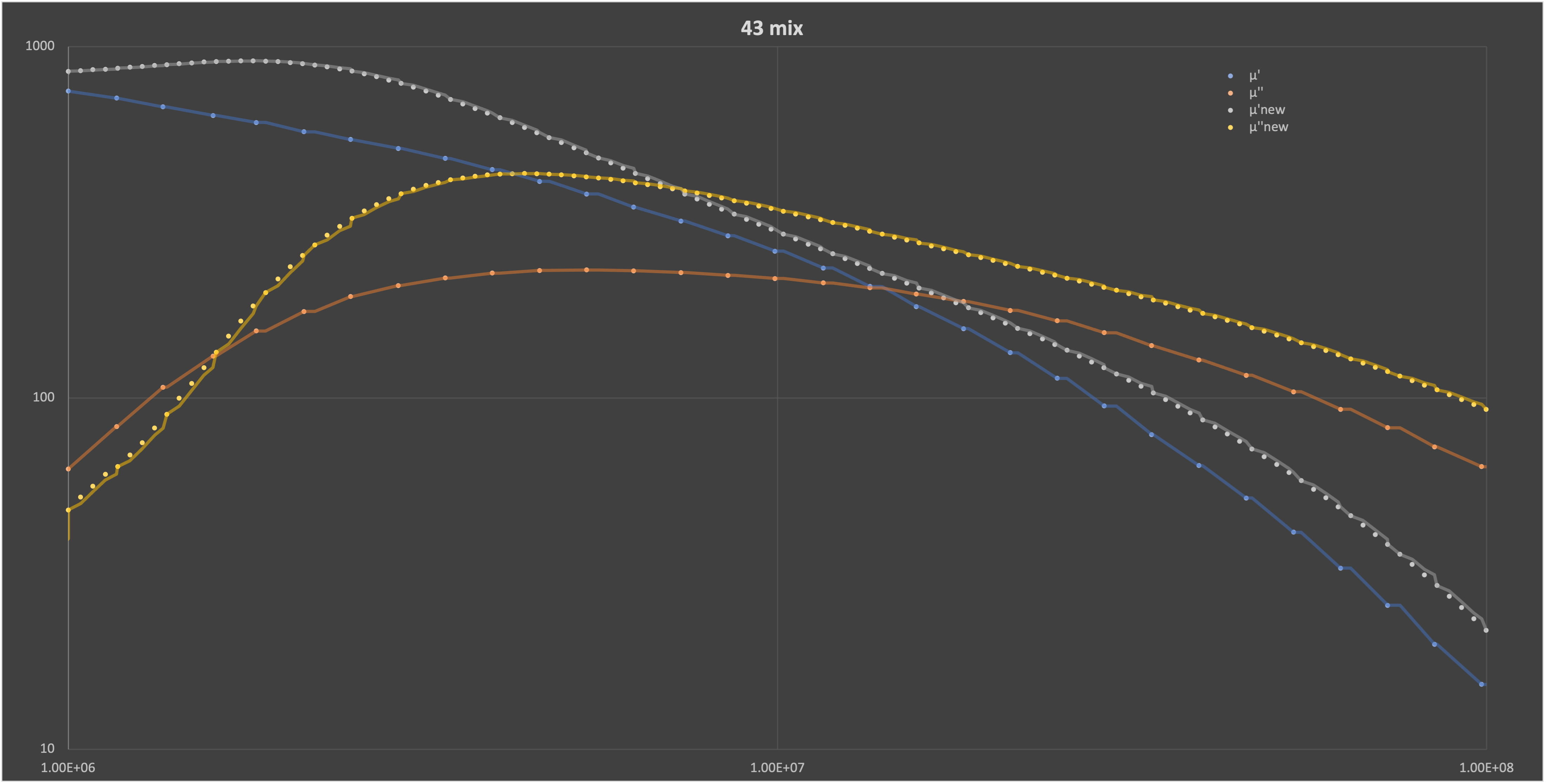
Or maybe Fair-rite just improved their measurements - there's no mention of any mix changes anywhere. Either way it makes me wonder what Fair-rite is doing...
I wonder if the new mix is still a good choice in HF.
Or maybe Fair-rite just improved their measurements - there's no mention of any mix changes anywhere. Either way it makes me wonder what Fair-rite is doing...
-
va3rr
- Posts: 54
- Joined: 30 Dec 2021, 21:39
- Location: FN25eg
- Contact:
Re: (tr)uSDX power, efficiency and filter optimisation
#43 ferrite has been used in QRP designs for years, as RF chokes and transformers. But if resistive losses are a problem for those contemplating 10 metre operation, perhaps a #52 or even #61 ferrite could be employed.
It's a little above my 'pay grade', though. I just like to solder...
It's a little above my 'pay grade', though. I just like to solder...
Slava Ukraini!
-
hb9hem
- Posts: 36
- Joined: 07 Jan 2022, 04:39
Re: (tr)uSDX power, efficiency and filter optimisation
Manuel posted two new videos on Youtube - very nice. The second one has an interesting bit of information at 6:40. I previously thought that L15 and C4 are just a LPF, but L15 also serves as energy storage! Might the lower Q of the new 43 mix make a difference here?
In any case, I don't know whether I'm barking up the wrong tree altogether... all I'm saying is that the 43s are not what they used to be - and for the advertised use-case (EMI suppression from 20 MHz to 250 MHz) the higher µ is an improvement, but what's the situation for other uses, e.g. transformers? In their white paper Fair-Rite don't have a simple answer. Hopefully someone with a higher pay grade can shed some light on all this.
In any case, I don't know whether I'm barking up the wrong tree altogether... all I'm saying is that the 43s are not what they used to be - and for the advertised use-case (EMI suppression from 20 MHz to 250 MHz) the higher µ is an improvement, but what's the situation for other uses, e.g. transformers? In their white paper Fair-Rite don't have a simple answer. Hopefully someone with a higher pay grade can shed some light on all this.
-
DL2MAN
- Posts: 718
- Joined: 30 Dec 2021, 19:18
- Contact:
Re: (tr)uSDX power, efficiency and filter optimisation
I even added some more insight today:
viewtopic.php?t=242
viewtopic.php?t=242
-
hb9hem
- Posts: 36
- Joined: 07 Jan 2022, 04:39
Re: (tr)uSDX power, efficiency and filter optimisation
Continuing with the L15, I built a contraption using 32 windings on a T130-2, i.e. a 12µH inductor with presumably higher Q than what can be obtained with the #43 core. I'm getting an improvement in 80m from 55% to 62% efficiency, in 60m from 60% to 64%, and otherwise there's hardly any change.
Bigger cores shift the high Q frequency ranges downward (see here), so that would be consistent.
It's a rather qualitative argument, 12µH is probably too low, but I would tentatively conclude that Q does matter for L15.
I'm beginning to gravitate towards the theory that it is multiple problems, not just one single problem, that lead to low efficiency in the *Rxxxx* kit
-
hb9hem
- Posts: 36
- Joined: 07 Jan 2022, 04:39
Re: (tr)uSDX power, efficiency and filter optimisation
Here is a neat approximate formula for the calculation of the temperature rise of inductor cores:
∆T/ºC = [(P/mW) / (A/cm²)] ^ 0.833
The T37-2 and FT37-43 have approximately 2.5cm² surface area, so the dissipated heat is
P/mW = 2.5 * (∆T/ºC)^1.2
Accordingly, that is 40-64mW per coil as I see 10-15ºC increases in some coils. That's nowhere near the 1-2W that are being lost, even if all five active coils were to heat up that much (5*64mW=320mW). I don't have a baseline to compare with, but I guess it is the three transistors that burn most of the excess power, i.e. the class E tuning is just not right - not too helpful a finding.
-
DL2MAN
- Posts: 718
- Joined: 30 Dec 2021, 19:18
- Contact:
Re: (tr)uSDX power, efficiency and filter optimisation
Well, you need a certain minimum inductance, so a Material 2 Core is the wrong choice as a choke inductor. In case of *Rxxxx* missing Efficiency is not L15. I watched it under thermal, and it does not get warm at all. PA Fets get warm (no surprise), LX1 and LX2 get a little bit warm, but T2 is almost as warm as the FETs.... So this might be a clue.
I´ve ordered some FT37-77´s to try in this position.
73 Manuel; DL2MAN
I´ve ordered some FT37-77´s to try in this position.
73 Manuel; DL2MAN
-
g7jur
- Posts: 35
- Joined: 18 Feb 2022, 22:49
Re: (tr)uSDX power, efficiency and filter optimisation
I am having the same problems with the *Rxxxx* kit.DL2MAN wrote: ↑18 Mar 2022, 08:24 OK guys, you´re not going to like this:
- We cannot give approval at this Time for *Rxxxx* Batch 1 and 2.
- There is a still unknown and unexplainable issue that causes low efficiency on all Bands
- I´m trying to work with you guys and *Rxxxx* so we can fix this and make the (tr)uSDX perfect
- The 1nF/1000pF Caps of Batch 1 are X7R Type (80/60/40m affected). This is probably why you see them heating up
- The 330pF of another Batch (Batch 2?) are X7R 50V Types (80/60/30m affected). So this will be probably even worse. But I did not see one yet, nor have I evidence to back that up.
This is partly our fault as well, as we pushed *Rxxxx* into market, when they expressed, they´d need more time and also were in the middle of moving into another workshop.
So I ask you, to please work with them and us, and try to help solving the issue without raising claims towards them.
Let´s try to be radio amatuers at it´s finest and help together here, please.
73 Manuel; DL2MAN
Philip G7JUR
-
hb9hem
- Posts: 36
- Joined: 07 Jan 2022, 04:39
Re: (tr)uSDX power, efficiency and filter optimisation
I think I'm finally beginning to understand how this class E business works. Doesn't the choice of L15 present a dilemma of sorts? I need a high inductance, therefore a high µ core (e.g. for HF some NiZn core). But I don't want core losses, i.e, equivalently, a high Q (hence some iron powder core). So, formulated as an optimisation problem: I chose the biggest core that fits, put as many windings as I can, then find the core material with the highest Q that achieves a minimum inductance? And that is #61 material...? Maybe two FT37-61s could be stacked side by side - there's just enough space - if 44µH suffices....so a Material 2 Core is the wrong choice as a choke inductor
-
g7jur
- Posts: 35
- Joined: 18 Feb 2022, 22:49
Re: (tr)uSDX power, efficiency and filter optimisation
Hope someone will find a fix for this problemhb9hem wrote: ↑27 Mar 2022, 08:52I think I'm finally beginning to understand how this class E business works. Doesn't the choice of L15 present a dilemma of sorts? I need a high inductance, therefore a high µ core (e.g. for HF some NiZn core). But I don't want core losses, i.e, equivalently, a high Q (hence some iron powder core). So, formulated as an optimisation problem: I chose the biggest core that fits, put as many windings as I can, then find the core material with the highest Q that achieves a minimum inductance? And that is #61 material...? Maybe two FT37-61s could be stacked side by side - there's just enough space - if 44µH suffices....so a Material 2 Core is the wrong choice as a choke inductor
Philip G7JUR
Last edited by g7jur on 28 Mar 2022, 21:40, edited 1 time in total.
-
Faraaz VK4JJ
- Posts: 215
- Joined: 30 Dec 2021, 21:56
Re: (tr)uSDX power, efficiency and filter optimisation
So, I spent a lot of thought on this problem over the weekend and had a interesting and useful conversation with Owen Duffy of OwenDuffy.net on the phone.hb9hem wrote: ↑27 Mar 2022, 08:52I think I'm finally beginning to understand how this class E business works. Doesn't the choice of L15 present a dilemma of sorts? I need a high inductance, therefore a high µ core (e.g. for HF some NiZn core). But I don't want core losses, i.e, equivalently, a high Q (hence some iron powder core). So, formulated as an optimisation problem: I chose the biggest core that fits, put as many windings as I can, then find the core material with the highest Q that achieves a minimum inductance? And that is #61 material...? Maybe two FT37-61s could be stacked side by side - there's just enough space - if 44µH suffices....so a Material 2 Core is the wrong choice as a choke inductor
Firstly, calculators such as miniringkern calculate their inductances based upon the initial permeability data released by manafacturers, which is measured at 10KHz (audio frequency). At RF, the permeability of a ferrite is a complex number and changes with frequency.
A wound toroid inductor is essentially a resonator with multiple resonances.
This document explains more.
https://owenduffy.net/files/EstimateZFe ... ductor.pdf
Owen has developed a tool that interpolates complex permeabilites based upon frequency for different ferrite materials.
He has a calculator for circular cross-section toroids that is frequency-dependent. It also takes into account equivalent series capacitance due to real-world imperfections in winding and interwinding capacitance.
https://owenduffy.net/calc/toroid3.htm
I calculated the theoretical values of the inductance, and the expected 'real' portion of Z (which would give I^2xR heat loss) at the different bands for FT37-43.


I then compared my theoretical model with a 22T winding on the FT37-43 core - it is close. Obviously, there will be some model imperfections due to excess capacitance, ferrite material tolerances etc but for
At 14.047MHz, the series inductance is 34.9uH. The Real part of Z was 988.6 Ω. Q of 3.1) This demonstrates that this core has fairly high ohmic resistances at RF with significant interband differences. The calculated impedance is also highly variable.
Similarly, if we look at the theoretical model for 7 turns at 14MHz on FT34-43, We can estimate the Real part of Z is 353Ω with a low inductance of Ls 2.75uH. This would give a Q of 0.68.

However, all of these assumptions are only valid for pure sinusoidal waveforms - of which class E is not. Therefore, my findings do not explain much at all - just pieces to a puzzle and should be considered as data on which to develop thoughts and experiment.
-
hb9hem
- Posts: 36
- Joined: 07 Jan 2022, 04:39
Re: (tr)uSDX power, efficiency and filter optimisation
This article could be of interest: Design of Choke Inductor in Class-E ZVS Power Amplifier. The current through L15 (the "choke") should be mostly DC, with only 5% or so ripple current on top, that's a few 10mA, here. If that's indeed the case, I²R is not a major issue, even at a rather terrible looking Q=0.68.
If I may venture a conclusion: If L15 produces significant losses then the ripple current is too high, which means class E is not well tuned for some other reason.
What are the losses? Using the ∆T from the heat camera, my back-of-the-envelope calculation says that L15 dissipates about 100mW - consistent with a ripple current of a few 10mA, but probably too crude an analysis.
And this raises the question about T1. 40Vpp at ANT_OUT is 14V RMS, at 5W that's about 0.3A, 1:7 transformed gives about 50mA through secondary windings, that would be 1W loss at R=400Ω. This calculation can't be right...
Users browsing this forum: No registered users and 1 guest