Page 1 of 2
High SWR and Power - Bad transformers connections ?
Posted: 22 Mar 2022, 22:45
by CR7BAQ
Hello all !
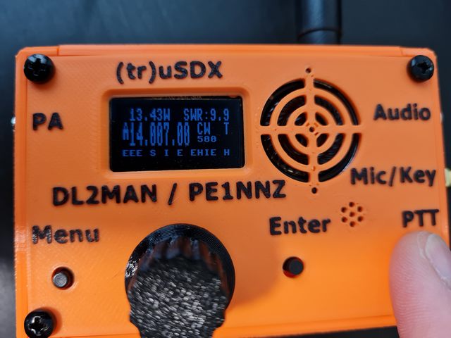
With a resonant antenna on 20m and 40m, Im having High SWR and Power in CW.
1st batch of *Rxxxx*.
With 13.8v power is about 13.4 W and SWR 9.9.
With 5v power is about 6 W and SWR 9.9.
Real power is:
13.8V
20m - 4W
40m - 3.5W
- 20220316_115123.jpg (52.9 KiB) Viewed 5243 times
Do I have the rigth connection on the T1 and T2 transformers ?
Thanks in advance.
Re: High SWR and Power - Bad transformers connections ?
Posted: 22 Mar 2022, 23:12
by wa2t
This is the problem I and a Chinese ham reported in a recent thread. I came up with changing the 68K resistors to 1K and the processor facing caps to 1M resistors as a fix. Yet to be determined if the developers agree with the fix or not.
73,
Robert, WA2T
Re: High SWR and Power - Bad transformers connections ?
Posted: 25 Mar 2022, 10:01
by Faraaz VK4JJ

Poor scraping of the enamel. There will be poor electrical contact. Please scrape thoroughly, get all the coating off and rework.
Re: High SWR and Power - Bad transformers connections ?
Posted: 25 Mar 2022, 20:46
by CR7BAQ
Faraaz VK4JJ wrote: ↑25 Mar 2022, 10:01
Poor scraping of the enamel. There will be poor electrical contact. Please scrape thoroughly, get all the coating off and rework.
Desoldered and scrap better the enamel. Soldered again up and down pcb. Still the same problem

Re: High SWR and Power - Bad transformers connections ?
Posted: 25 Mar 2022, 21:43
by DL2MAN
Please measure on Pins "FWD" and "RVS" on Inter-PCB Connector while TXing into Dummy Load.
At SWR 1 you should see Near Zero Voltage on one and Some Voltage (around 2,5V @5W) on the other.
If that´s not the case, there´s some issue around SWR Transformers (No Continuity at some point)
If you see the Voltages there, and it still shows Bad SWR most likely your related Input Pins of AtMega are fried. I had the same one time, and I needed to exchange AtMega to solve it.
73 Manuel; DL2MAN
Re: High SWR and Power - Bad transformers connections ?
Posted: 27 Mar 2022, 15:39
by CR7BAQ
DL2MAN wrote: ↑25 Mar 2022, 21:43
Please measure on Pins "FWD" and "RVS" on Inter-PCB Connector while TXing into Dummy Load.
At SWR 1 you should see Near Zero Voltage on one and Some Voltage (around 2,5V @5W) on the other.
If that´s not the case, there´s some issue around SWR Transformers (No Continuity at some point)
If you see the Voltages there, and it still shows Bad SWR most likely your related Input Pins of AtMega are fried. I had the same one time, and I needed to exchange AtMega to solve it.
73 Manuel; DL2MAN
Thanks for your answer Manuel.
Measures with 13.8V
RX:
FWD - 1.85 V
RVS - 1.64 V
TX:
FWD - 1.8 V
RVS - 2.5 V
When Im measuring the voltage on RVS with voltmeter, the power on the screen is correct !
When Im measuring the voltage on FWD with voltmeter, the SWR on the screen is always around 2.2-2.4, even if I have a good (1.5 or less swr) or bad SWR.
Checked again all the SWR bridge circuit and all appears to be ok.
What could lead this behavior when Im measure the voltage ?
Are the Input Pins of AtMega fried as you guess?
Re: High SWR and Power - Bad transformers connections ?
Posted: 28 Mar 2022, 15:57
by NEW BOY
HI, CR7BAQ, I have the same problem as you, but my power seems to be normal, that is, the SWR shows 9.99. Is your problem solved?
Re: High SWR and Power - Bad transformers connections ?
Posted: 28 Mar 2022, 16:11
by CR7BAQ
NEW BOY wrote: ↑28 Mar 2022, 15:57
HI, CR7BAQ, I have the same problem as you, but my power seems to be normal, that is, the SWR shows 9.99. Is your problem solved?
Hi NEW BOY.
Not yet.
Re: High SWR and Power - Bad transformers connections ?
Posted: 29 Mar 2022, 17:46
by DoubleHaul
Seeing the same thing w the *Rxxxx* batch #2 kit. I get a reported 0 power out at 9.99 swr when transmitting into a dummy load. I do get voltage on fwd, none on rvs when transmitting. The SWR measurement occasionally drops to 1.0 while measuring. My multimeter testing was done on a 5V USB pack, will have to test again on my bench power supply.
Receive, relays, filtering, etc all seem to be working fine. I can actually hear myself w another radio when transmitting into the dummy load. I also tuned my filter inductors using a nano vna so I'm convinced those are good as well.
Should the voltage on the RF pin on the pcb interconnect match or be close in magnitude to the voltage read on the pads that connect the single turn through T1?
Re: High SWR and Power - Bad transformers connections ?
Posted: 29 Mar 2022, 23:10
by Faraaz VK4JJ
I get a reported 0 power out at 9.99 swr when transmitting into a dummy load.
Very likely to be swr bridge poor contact between wire and pcb.
Re: High SWR and Power - Bad transformers connections ?
Posted: 29 Mar 2022, 23:33
by DoubleHaul
Faraaz VK4JJ wrote: ↑29 Mar 2022, 23:10
I get a reported 0 power out at 9.99 swr when transmitting into a dummy load.
Very likely to be swr bridge poor contact between wire and pcb.
Is it possible to test this with a multimeter? I've replaced the single turn jumpers on both T1 and T2 (T2 twice now) thinking the same thing.
Edit: I reflowed the 7 turn connections on T1 and T2 (I'm completely convinced there is no enamel on the single turns). Immediately following the reflow I read ~14W power out on 20m with a 9.99 SWR into a dummy load. After changing bands it reverted to 0W power, even after returning to 20m. Maybe I will go ahead and pull both T1 and T2 completely off yet again.
Edit 2: replaced T1 and T2 completely. I now get an accurate SWR reading from what I can tell. It still registers 0 power out on both 5v and 13.8v, but I can hear it on my other radio... Need to rig up a way to test power. I'd be fine with the power out not displaying so long as I get some power.
Re: High SWR and Power - Bad transformers connections ?
Posted: 08 Apr 2022, 10:57
by NEW BOY
CR7BAQ wrote: ↑28 Mar 2022, 16:11
NEW BOY wrote: ↑28 Mar 2022, 15:57
HI, CR7BAQ, I have the same problem as you, but my power seems to be normal, that is, the SWR shows 9.99. Is your problem solved?
Hi NEW BOY.
Not yet.
HI, CR7BAQ,Is your problem solved now?
Re: High SWR and Power - Bad transformers connections ?
Posted: 06 May 2022, 10:30
by EA5M
Hello everyone.
Same problem here.
I have checked the circuit and it seems to be all right around transformers T1 and T2.
New review.
I have verified that when it is working for a few minutes. Everything works well.
Look at the photo:
73 de Dani EA5M
Re: High SWR and Power - Bad transformers connections ?
Posted: 27 May 2022, 08:19
by sv5fri
Hello,
I have same exact problem after few minutes when operated it come back to normal.
Any idea?
Re: High SWR and Power - Bad transformers connections ?
Posted: 14 Jul 2022, 08:29
by Ohwenzelph
When I first asked about this I was told the bnc to sma was probably loose. You can see the same thing happen momentarily to Manuel in "(tr)uSDX - Tuning the RF Section for Power and Efficiency"
https://youtu.be/qN7hHsvcNMM at about -3.25 from the end when he says "whoaooo ooooh"
I wonder what it is and why it's sometimes momentary and other times sticks?
Re: High SWR and Power - Bad transformers connections ?
Posted: 14 Jul 2022, 20:34
by wa2t
If you have the boards out of the case and add "the magic finger" to the components after the detector diodes, the problem goes away for as long as your finger is there, this has been my experience. In my opinion, there is a circuit problem in this area. I revised my units accordingly (component changes) and the problem is gone, never to return. I have made some posts about this previously.
73,
Robert, WA2T
Re: High SWR and Power - Bad transformers connections ?
Posted: 14 Jul 2022, 23:45
by Ohwenzelph
So,
"68K resistors to 1K and the processor facing caps to 1M resistors as a fix. Yet to be determined if the developers agree with the fix or not."
So far I do not think we have heard from "the develpers" about your fix. Are the "64k resistors" R5 and R6 on the RF board? And are the "processor facing caps" C31 and C39 on the main board? What do you think is happening and how do you think your mod is fixing it? Sometimes it just seems to just stop happening, possibly making it hard to known what "fixed." I do not understand any of it but am curious.
Tnx
JT aa1of
Re: High SWR and Power - Bad transformers connections ?
Posted: 16 Jul 2022, 16:21
by wa2t
All parts concerned are on the RF board. As for what they do, they 1. Lower the impedance presented to the ATMEGA (reference the data sheet info I quoted) and 2. removal of the second cap stops the “charging” effect I noticed on problem units (values climbing over time).
73,
Robert, WA2T
Re: High SWR and Power - Bad transformers connections ?
Posted: 16 Jul 2022, 22:30
by Ohwenzelph
So, then the "processor facing caps" are C7 & C8 on the RF board, yes?
Re: High SWR and Power - Bad transformers connections ?
Posted: 17 Jul 2022, 15:31
by wa2t
Ohwenzelph wrote: ↑16 Jul 2022, 22:30
So, then the "processor facing caps" are C7 & C8 on the RF board, yes?
Correct. Interesting about C31 and C39 though, I had not looked for or even thought there were additional caps (connected to the same lines) beyond C7 and C8 on the RF board.
Regardless, I think this (now) fully describes what I saw, what I did, and what the results were. If you have any further questions, let me know.
73,
Robert, WA2T
Re: High SWR and Power - Bad transformers connections ?
Posted: 29 Aug 2022, 06:42
by Randal007
I am having this exact same issue with efficiency reading, the magic finger fixes mine. Whats strange is that it used to work or so i thought but now i always read 99% efficiency unless i put my finger on that spot and then it reads the correct value around 80% efficiency. I kinda want to change the resistors and the 2 caps to fix it. What does DL2MAN think o0f this mod.
I also did triple check my toroids and all the pcb paths RVS reads 2v and FWD reads near 0 and I get 99%efficiency????? My SWR reads perfect at 1.0 into a dummy load fyi.
Anyone have any ideas I am at a loss?
Re: High SWR and Power - Bad transformers connections ?
Posted: 10 Oct 2022, 06:14
by agtrusdx
I just finished assembling mine and had the same problem when I first powered on. SWR reads 9.9 and power is 1.24W on 13.8v. I did continuity test between the center conductor of the sma and the T1, and measured no continuity. I resoldered the center conductor of the sma to the pcb, retest continuity and was good. Power now reads 5.08W and swr 1.01. Efficiency is 99.99% though. I will try to make a contact and if successful, I will just leave it likethat.
Re: High SWR and Power - Bad transformers connections ?
Posted: 29 Oct 2022, 13:00
by n6mgn
After assembling my unit, I noticed the dreaded high SWR (9.9). Turns out there was leakage from the 12V line to the REV (and also to the FWD) line at the inter-board connector. A static 5.5 volts on REV, and 3.5 on FWD. Probably from residual solder flux under the connector. I was going to try adding a DC load/return-path at the inputs to the ADC, but my scope probe slipped and shorted 12V to the REV line and smoked my main board.
I believe you should add a 56K resistor to ground for the FWD and REV signals, otherwise the impedance is too high. Simply touching the lines with a finger changes the readings. I was getting about 2.5 watts on 20M (using my Motorola R2600). All the 5V chips on my main board are probably toast, so my adventures into (tru)SDX have ended.
72 de N6MGN
Re: High SWR and Power - Bad transformers connections ?
Posted: 01 Nov 2022, 16:02
by ng1p
I have built 3 full kits so far. The original low band worked fine. Both of the new ones with the updated RF board using Q5 and the updated T2 both show 9.99 SWR and 0 power out as talked about. The two new kits are one for the classic bands and the other for the high bands. Both radios work great it’s just the power/SWR function does not. What is the true fix for this? I assume anyone building the newer boards will have the same issue.
Can someone point me to a post that talks about what components need to be replaced to make this work?
Thank you Bill NG1P
Re: High SWR and Power - Bad transformers connections ?
Posted: 08 Nov 2022, 21:32
by ng1p
So reading over what I see in this thread is to mod the RF board (new classic and high band) by replacing R5 and R6 from 68k to 1k resistors and replace C8 and C7 with 1M resistors.
Can anyone confirm that this will resolve the meter readings of power and SWR and do I have this correct?
Thank you
73 Bill NG1P